The complete modularity of the system allows to set the joint to meet all the different installation needs:
• Line Joint (to join two OPGW pieces)
• Terminal joint (to join the external OPGW with the internal dielectric cable which comes from the substation; if required, the entrance for the OPGW can be equipped with a special insulator.
• Branched or jointed junction (to branch or to extract secondary OPGWs from the main OPGW)
• Intermediate jointed junction (to join one or more dielectric cables from the OPGW Network to connect regeneration substations)
Available in 2 different standard sizes for the same number of capacities:
• With short cap (capacity: up to 240 fibers with Single Element management)
• With long cap (capacity: up to 408 fibers with Single Element management)
Available in 2 different standard configurations:
• With a suitable base for the equipment of 4 circular doors max
• With a suitable base for the equipment of 6 circular doors max
Special configuration
• Terminal joint with opposing ports for installation on limited height portals.
Functional specs
Cable inlets
• Four or six slots (closed with special removable caps) can be equipped at a later time using special cable glands.
• A wide and complete range of cable glands is available (for both OPGW and dielectric cables).
Installation
• The product is mostly designed for installation on truss. However, a wide range of fixing brackets allows wall, pole or street installation.
• The cable inlet located on the same side allows better installation in every condition.
• Removable cable anchoring devices allow the heads to be prepared outside the joint.
Fiber management
• Modules equipped with boards for the management of the Single Element (all the fibers from the same slot or tube are allocated within the same junction board) or with boards for the management of the Single Circuit (only two fibers of the same functional circuit are allocated within each board) are available.
• The junction boards can be equipped with different supporting devices for:
– Junction protection (heat shrink, Crimp-Splice BOSH...)
– Mechanical joints (Fiber-Lock 3M...)
– Passive optical components (splitter...)
• Guided fiber paths for active control of minimum fiber bend radius of 30 mm.
• The fibers are guided and managed protectively in the same structure that supports the junction boards:
the reconfiguration of the wiring can be performed with extreme ease.
• The junction boards are individually accessible and allow full access to the junction areas without the risk of introducing disturbances on the fibers located in the adjacent boards.
• The complete modularity of the system allows network expansions and/or reconfigurations to be performed even after the first installation.
Maintenance
• The joint allows quick and easy access (opening and closing) without the use of additional consumables.
• A standard pressure test valve allows to control the airtightness of the joint after each opening and closing operation.
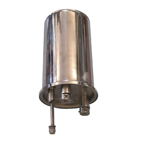
MJS-OPGW Guard Rope Joint Box